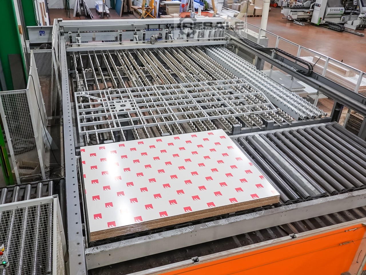
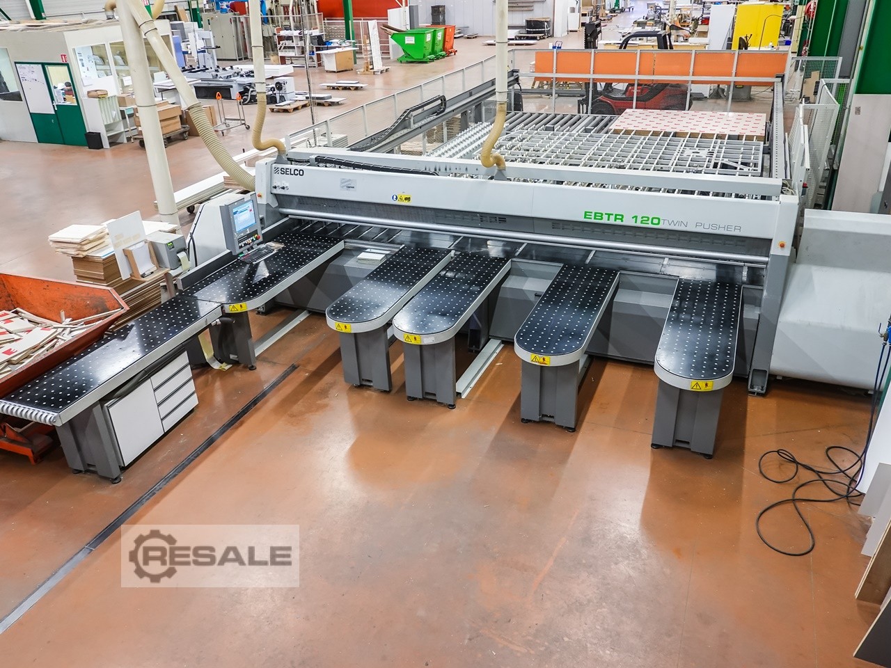
SELCO EBTR 120 Twin Pusher - 5600 mm
Numerically controlled sawing center with one cutting line, with two
independent pushers and rotating platform for automatic
pre-cutting.
Automatic panel loading, directly from a precision lift table.
MAIN TECHNICAL CHARACTERISTICS
Maximum cutting length: 5600 mm
Max stroke of the auxiliary pusher: 4300 mm
Maximum protrusion of the plank from the worktop: 122 mm
Maximum opening of the panel clamps: 110 mm
Lift table with direct loading: 5600 x 2200 mm
Minimum panel dimensions in loading position: 2440 x 1220 mm
Minimum thickness that can be loaded from the lift table: 10 mm
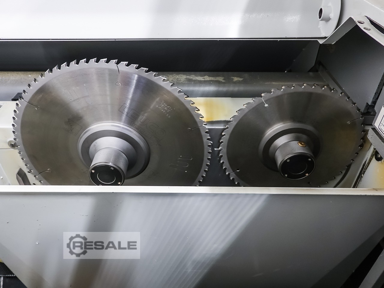
Main blade ⌀ 430 mm, 18.5 kW / 50Hz (25 HP)
Scoring blade ⌀ 200 mm, 2.2 kW / 50 Hz (3 HP)
Brushless motor for movement:
- Trolley blades - speed 1 -150 m/min
- Main pusher - maximum speed 100 m/min
2 rear roller side alignment device with automatic positioning (60 mm
to 2200 mm)
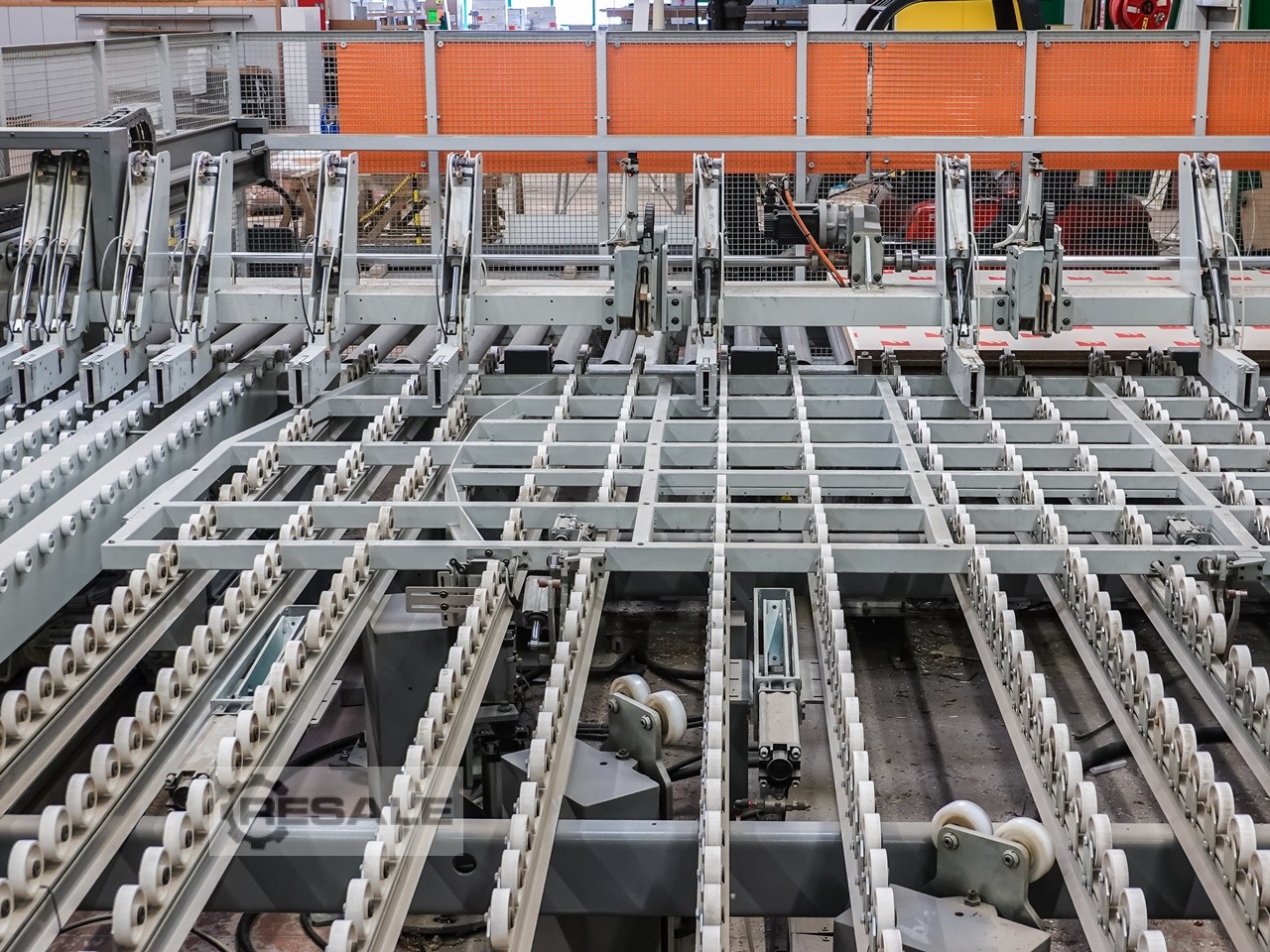
Rotary platform for automatic pre-cutting
To perform one or more pre-cuts
The touming station consists of a platform that lifts and rotates the
stack of parts by 90°
For rotation, the clamps are held in place by 4 locking devices
The stack of stacks is aligned by devices before and after rotation
As soon as the pre-cutting cycle is complete, the main part of the
stack is transferred to the rotating station, if necessary, and
rotated again by 90°, while the pre-cut part is sent to the
cross-cutting
2 stack alignment devices, before and longitudinal, after rotation
TWIN PUSHER auxiliary pusher
Auxiliary pusher for simultaneous execution of several cutting
phases
Operates in sync with the main pusher
The 2 pushers are managed by a software which, depending on the
cutting pattern and the necessary machining phases, selects the
grippers of the various pushers to be inserted into the machining area
in order to carry out as many simultaneous cutting cycles as
possible.
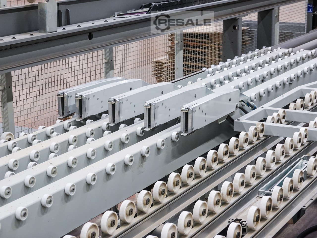
The auxiliary pusher is made up of 4 independent clamps and can mount
a fifth (optional).
Automatic expulsion of cut panels
4 pneumatic clamps with independent lifting in the transverse area of
the main pusher (placed 70, 180, 390, 600 mm from the bracket)
4 pneumatic clamps with independent lifting in the longitudinal area
of the main pusher (placed at 2235, 3845, 4650, 5450 mm from the
square)
4 pneumatic clamps with independent lifting in the auxiliary pusher
(placed at 70, 180, 390, 600 mm from the bracket), 5th at 810 mm
Front support planes
5 air cushion tables with rounded profile 2050 x 850 mm to maximize
the width available for simultaneous cross-cutting of strips
1st table extension 2050 mm
Loading lift table
Industrial Frame
Heavy one-piece structure, perfect stability
Guide rails of the carburized and calibrated blade-carrying charlot
The tool carriage supports the main blade and the scoring blade in
front of it
Pressing unit
Side alignment unit with two independent rollers
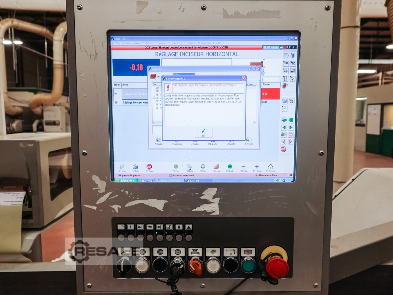
Control on Windows XP PC, 17" screen
With cutting diagrams, lists, manual cuts, simulation, diagnostics,
online help, maintenance, statistics and parameters
ADDITIONAL EQUIPMENT INCLUDED
"QUICK CHANGE" SYSTEM
For quick and safe replacement of the main blade and scoring blade
"DIGISET" FUNCTION
For electronic adjustment (directly on the numerical control) of the
horizontal and vertical alignment of the scoring blade K5658589 with
the main blade
SECOND RUBBER ROLLER
For Lateral Alignment Device
ADDITIONAL PNEUMATIC GRIPPER WITH 90° VERTICAL MOVEMENT
FIFTH ADDITIONAL PNEUMATIC CLAMP FOR AUXILIARY PUSHER POSITIONED 810
MM FROM THE SQUARE
PUSHER FOR START CYCLE REMOTE CONTROL INCL. EMERGENCY PUSHER
Positioned next to the 2nd air cushion
"P.FS." FUNCTION FOR CROSS-CUTTING (POST-FORMING)
ADVANCED WORK FNCTION
"Macro" function: execution of a groove inside a program
MOTORIZED CONVEYOR AT THE ENTRANCE OF THE LIFT TABLE
RIGHT SIDE ENTRY ON LIFT TABLE
MOTORIZED ROLLERS ON LIFTING TABLE FOR SAW 5600 x 2200 mm WITH SIDE
LOADING
INVERTER ON THE LIFT TABLE FOR QUICK LOWERING OF THE TABLE
OFFICE IT PART
"OPTIPLANNING" SOFTWARE PROFESSIONAL VERSION:
Possibility to group a large number of cutting lists (even for
different materials) so that they can be optimized in a single job
Containing the "IMPORT FILE" function
To edit lists of parts to be manufactured and/or materials to be
cut
Automatic management of the panel warehouse and the waste that can be
recovered
PANEL AND OFFCUT STOCK FUNCTION
"QUICK OPTI" SOFTWARE
For optimization of cutting patterns
ELECTRONIC LABEL PRINTER WITH PEELER ON BOARD THE MACHINE
Dust extraction:
1 main suction inlet 200 mm
2 upper suction inlets on the 100 mm cutting line
1 upper suction inlet at the end of the presser 150 mm
Suction flow required 7000 m3/h
Pneumatic Feeding: 260 Nl/min

 France
58000 Challuy NEVERS
France
58000 Challuy NEVERS
