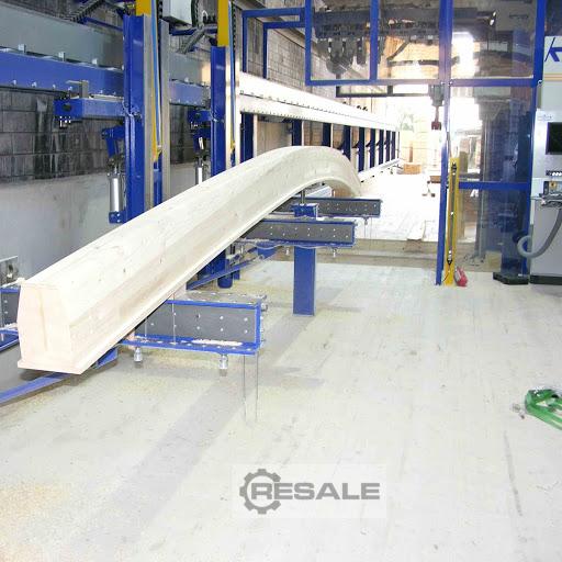
A used LIGNAMATIC from KRÜSI
Year of construction 2010
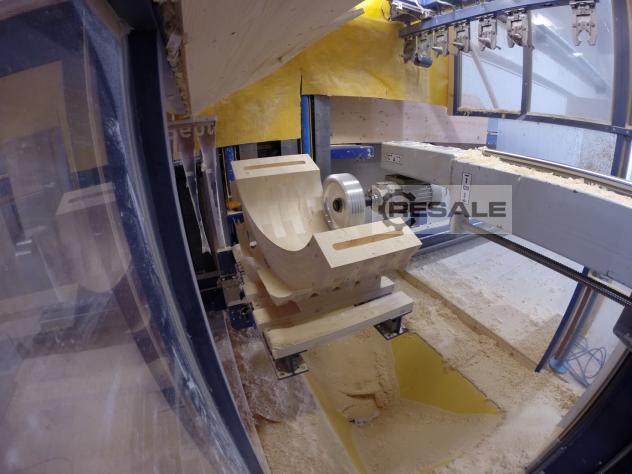
Free-form machining at its best
Machining centre for the highest quality engineering
Timber construction, carpentry special joinery, prefabricated house
and element construction.
We are currently happy to offer a second-hand carpentry machine from
Krüsi that is second to none.
Complete with tool magazine, track system and 6 pieces of clamping
trolleys.
Max. cross-section that can be machined from 6 sides without
turning
approx. 1400 mm in Y axis x approx. 1200 mm in Z axis up to a length
of approx. 28 m
A and B final drive with Wittenstein / Alpha Robot gearbox
With rigid rail guide for the clamping carriages.
Space required:
Total length of the machine – 46,000 mm
Total length of the guideway – 45,000 mm
Total height of the machine system incl. protective cover – 3,520
mm
Total width of the machine – 6,600 mm
Machine system with protective cabin and light barriers incl. control
cabinet complete with
Control without joinery program. ( On request )
Simulation and collision monitoring
Collision monitoring on the system
Technical processing with electrical diagram,
Software PLC, software CNC and documentation
in German.
Technical general machine description
LIGNAMATIC:
Total length of the machine system 46,000 mm
Total height of the machine system incl. protective cabin 3,520 mm
Total width incl. protective cabin 6,600 mm
Machining Center (Robots)
Elements
The stable and heavily built machine stand is welded from steel and
very torsion-resistant due to its hollow body. It is precisely
machined at the necessary points and has screwed-on, continuously
supported, hardened and ground precision round steel guides Ø 40 mm,
on which the cross guide support with boom is held or guided
(Z-guide). The counterweight for the boom with milling motor is
suspended from two heavy precision link chains. It is fully protected
and safely housed in the hollow body of the machine stand. The load is
deflected by two large sprockets.
The cross guide support is made of special cast aluminum alloy because
of its weight. To ensure that the stability of the stand continues to
have an effect, it is very thick-walled and well ribbed. The cross
guide support is equipped with 6 radial ball guide bushings vertically
and 4 pieces horizontally for high loads and high rigidity.
The boom is made of a square steel hollow section and has welded-in
reinforcements. It is precisely machined in the necessary places. It
is held and guided by two continuously supported, tightly screwed,
hardened and ground precision round steel guides Ø 40 mm in the
radial ball guide bushings of the cross guide slide. The boom can
therefore be moved very smoothly and without backlash at high speed
over the entire travel range via the cross guide carriage in the Y and
Z directions.
A rotary axis B is installed inside the boom and is deposited in
large-dimensioned guides. It essentially consists of a large,
tube-like hollow body. At one end is attached a bracket housing for
the rotary axis A, on which the main spindle motor is finally held
swivelling on all sides. At the other end is a torsionally rigid
special coupling for mounting on the rotary drive B. The rotary axes A
and B are driven and deposited by Harmonic Drive robot motor gears.
Final drives
The cross-guide support including boom is driven in direction Z by an
AC servo motor with holding brake and built-in absolute resolver built
in the latest technology. The power is transmitted via toothed belts
to the ball screw Ø 40 mm x 40 mm pitch. This lead screw is
absolutely backlash-free and has a very high efficiency.
The boom is driven in direction Y by an AC servo motor built in the
latest technology with an absolute resolver. The power is transmitted
via toothed belts to the ball screw Ø 40 mm x 40 mm pitch. This
threaded spindle is also absolutely backlash-free and has a very high
degree of efficiency.
The B axis in the boom can be swivelled by approx. 450 degrees
parallel to the Y axis. The swivel movement is carried out by a
Harmonic Drive robot motor gearbox. The absolute turret is mounted
directly on the engine.
Axis A can be swivelled by approx. 200 degrees. The swivel movement is
carried out by a Harmonic Drive robot motor gearbox with absolute
resolver.
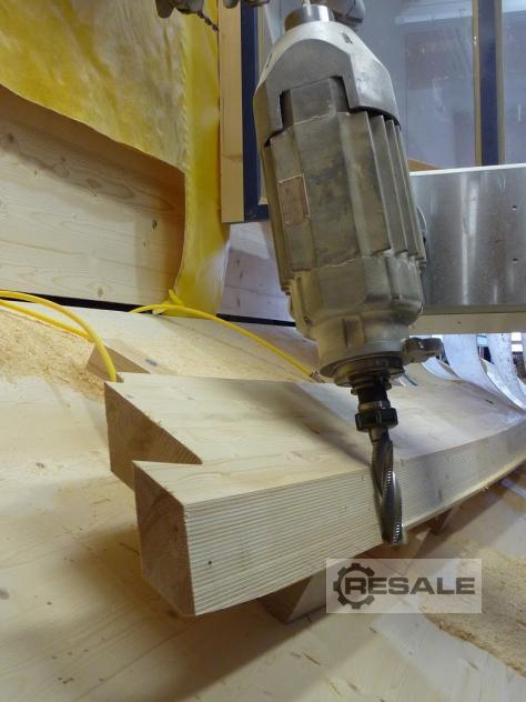
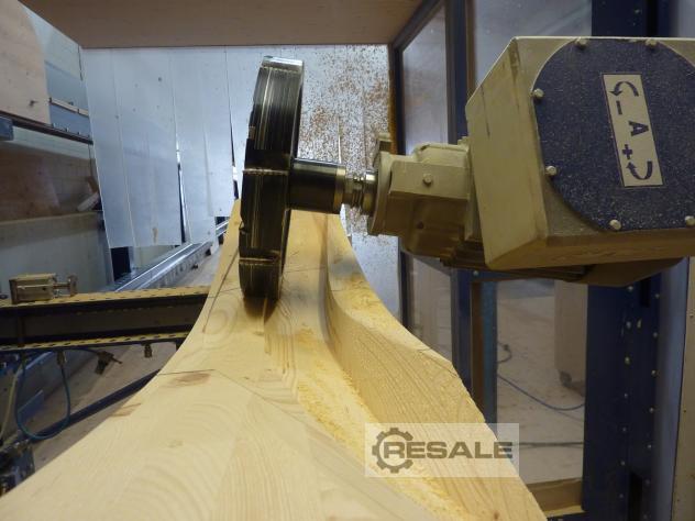
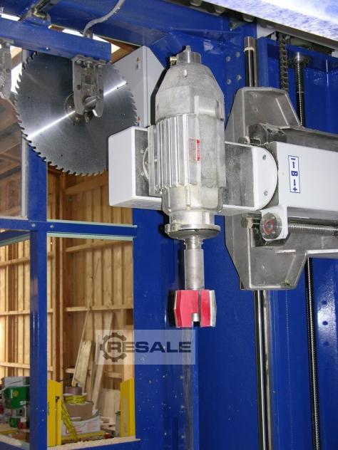
The main spindle motor
The winding of the main spindle motor is similar to that of a normal
three-phase motor (3 phases asynchronous). It is very long according
to the engine size and small in diameter. To ensure that the speed of
the motor can be controlled within wide limits, a special magnetic
sheet metal package is installed. The speed control is done from the
control system via an electronic current regulator (frequency
controller). The motor axis is designed like a machine tool main
spindle and is also equipped with special main spindle roller
bearings. As a continuous hollow spindle, it is equipped with ISO 40
steep taper at the front. Inside the hollow spindle is a tool feeding
device preloaded by a spring package, which can be released by an
attached special hydraulic cylinder. It is therefore not possible for
the tool to fall out in the event of a drop in current, air pressure
or hydraulic pressure. The tool feeding device is equipped with a
channel for compressed air so that the tool cone and the receiving
cone in the spindle can be blown out when changing tools.
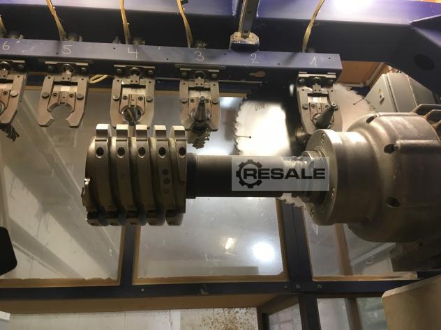
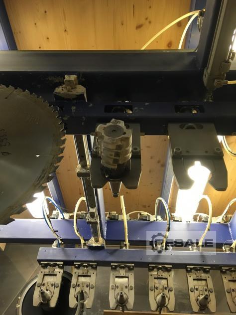
The tool magazine
The tool magazine is mounted on top of the stand and is designed as a
double-sided row magazine. The tools are mounted horizontally and held
in place by self-locking grippers. The gripper pliers can be opened
pneumatically. A total of 15 (16) storage spaces are available.
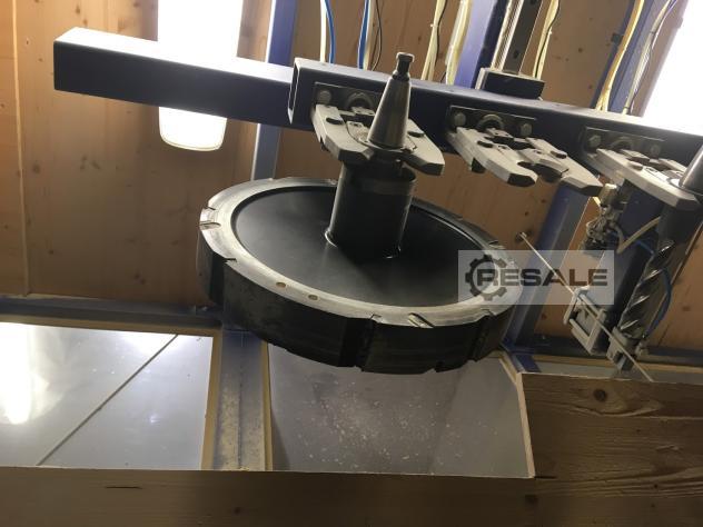
Tool change (short description):
When the tool is transferred, the in-line magazine in question moves
against the main spindle motor, which is ready in the corresponding
tool position, and thus transfers the tool to it. At the same time,
the main spindle motor blows off the cone of the tool
When the tool is taken over, the feed pin is caught by the feed pliers
and pulled in by the disc spring packet. Sensors are used to monitor
whether the tool is properly retracted and held. The machine can even
detect the absence of the feed pin on the cone. Only afterwards does
the gripper open and the main spindle motor moves away with the tool
downwards. During processing, the magazine moves outwards. When the
return order is issued, the corresponding row magazine retracts and
the gripper clamps open. The main spindle motor positions itself in
the correct position in a preparation position and then moves from
below into the open gripper. The gripper clamps close, the main
spindle motor releases the tool and the magazine extends with the
tool. The main spindle motor is positioned in the position of the next
tool, etc. Practically all motion sequences are monitored by the
control system via sensors.
Track system
The track system is set up along a concrete wall. The posts made of
DIN T-beams are attached to the concrete wall every 3,000 mm. An
extremely strong and secure anchoring is necessary to ensure the
precision of the guideway for years. The upper longitudinal members
made of DIN T-beams, which are precisely machined at the necessary
points, serve as a holder for the hardened and ground precision round
steel guide with Ø 40 mm, which is supported and bolted with a saddle
every 200 mm. The lower Star profile rail guide is mounted on a
special retaining rail made of square hollow section and angle steel.
On the precisely machined retaining rail, the hardened precision rack
is also screwed on absolutely parallel. The guide rails are mounted in
such a way that they are largely protected from dust and damage. The
energy chain guides for the 4 tensioning cars are built over the
entire length of the track.
Clamping trolley
The clamping stringers are held and guided on top of 2 pieces of
linear bearings with super ball guide bushings and at the bottom with
2 pieces of guide cars on the track of the track system. The support
arm and also the carriage breast are mechanically precisely machined.
Two rows of mounting holes are attached to the support arm for
inserting the B51228599 horizontal clamping cylinders. The press beam
can be adjusted in height by motor means of a threaded spindle and can
also be swivelled up by a compressed air cylinder. A special toggle
joint automatically locks the press beam in the swivelled position. A
compressed air cushion built into the press beam is used for vertical
clamping. This means that workpieces of different thicknesses can be
clamped at the same time. Each of the four clamping cars is equipped
with a state-of-the-art AC servo gear motor with holding brake with
built-in absolute resolver. The power is transmitted via a hardened
gear wheel to the rack of the track system. Each car is equipped with
two energy drag chains. The power and control cables are routed
separately. This avoids interference impulses that would arise from
the parallel routing of such long cables.
Hydraulic power unit with pressure accumulator
It supplies the machine with pressure oil to release the tool feed in
the main spindle motor.
General
All movable cable lines are routed in energy chains. The majority of
the cables are equipped with multi-pole plug-in contacts on the
machine and control side. The easily accessible junction boxes, which
are equipped with plug contacts, make it possible to quickly find
possible contact faults.
Specifications
Workspace
Total length of the machine system according to customer requirements
normal = 46,000 mm
Total height of the machine system incl. protective cover 3,670 mm
Total width incl. protective hood approx. 6,600 mm
Length of the X-axis guideway 45,000 mm
Number of trolleys 6 4 pieces
Max. transverse travel of the Y-axis boom 1,750 mm
Max. vertical travel of the boom Z-axis 2,030 mm
Swivel range A-axis approx. 200 degrees
Swivel range B-axis approx. 450 degrees
Support width of the clamping carriage 1,300 mm
Working width Y-axis 1,200 mm
Height of the tension beam over support 0 - 300 mm
Travel speeds
Rapid traverse speed X-axis 57 m/min.
Rapid traverse speed Y-axis 40 m/min.
Rapid traverse speed Z-axis 40 m/min.
Feed speed X-axis 0 - 30 m/min.
Y-axis feed speed 0 - 30 m/min.
Feed speed Z-axis 0 - 30 m/min.
Main spindle motor 3-phase asynchronous
Nominal speed 3,000 rpm.
Max. speed 10,000 rpm.
Speed range 300 - 6,000 rpm
Nominal power approx. 20 KW
Rated current 15.3 A
Tool holder DIN 69871 ISO 40
Pull-in bolt DIN 69872 Type A
Tool retraction force 9,800 N
Spindle diameter in the front bearing Ø 60 mm
Tool magazine - automatic tool change
Magazine type: double-sided series magazine
Number of tool positions (16) 15
Max. tool diameter Ø 600 mm
Max. tool length 400 mm
Max. tool weight for length up to 100 mm from spindle breast 15 kg
Max. tool weight for length up to 150 mm from spindle breast 12.5
kg
Max. tool weight for length up to 250 mm from spindle breast 10 kg
Max. tool weight for lengths over 250 mm from spindle chest 7.5 kg
Max. capacity of the stacks with 15 fully occupied seats:
1 x
Ø 600 + 7 x Ø 200 +7 x Ø 160
Tool diameters larger than 200 or 160 mm are possible with free
adjacent spaces.
Engine hydraulic power unit 0.37 KW
Total connected load of the machine KVA
Pre-fuse at 400 volts 80
Sale from location as seen without warranty and guarantee
Costs for dismantling, packing, loading, transport, etc. are not
included in the purchase price.
Payment immediately upon receipt of the invoice without deduction.
The facility can be visited at any time by appointment.
Available from approx. Dec. 2025 / Jan 2026

 Germany